
We report on characterization of a variety of coating materials and designs with this adaptive method. This technique allows for the test regimen to be tailored to the specific surface under consideration. Test sites in zones with no detectable defects are also included. With defects of interest now centered on the damaging beam, the problem of higher-order spatial variation in the beam profile is greatly reduced.

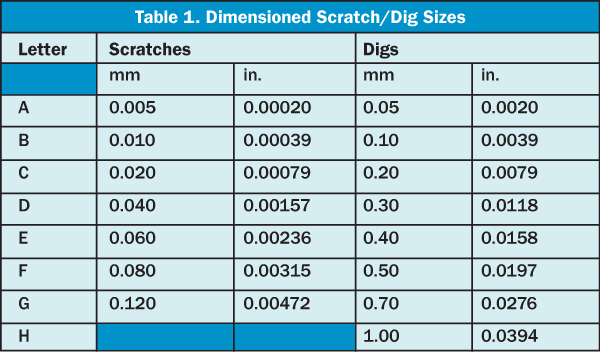
A map of defect locations and sizes on a test surface is compiled, and a set of test sites and corresponding fluences based on that map is then generated. In an effort to make this process both more efficient and less susceptible to uncertainties, we have now developed an adaptive test strategy that puts defect identification and analysis into the loop. However, in all this work the test sites were always in a predefined array, and the association of defects with damage events was done only after the fact. Previous work on this problem using REO’s automated laser damage threshold test system has included linking damage events in HfO2/SiO2 high reflector coatings with visible pre-existing defects, and using a probability per defect based on size and local fluence to generate predictions of damage events in subsequent coating runs. Standard techniques for characterizing laser damage are ill-suited to the regime in which sparse defects form the dominant damage mechanism. This yields one order of magnitude reduction in the number of undetected damaged sites. It was also compared to a generally used visual laser damage detection procedure, which has a success rate of 88.6%. The proposed method was tested on a sizeable dataset of images yielding 98.8% of damage detection efficiency. The evaluation algorithm is built of computationally less demanding mathematical operations to enable fast execution which is vital for monitoring at high repetition rates. This mimics the ability of the human eye to distinguish features from their surroundings. Besides, it takes into account the spatial extent of a damage spot by nonlinear image filtering to separate damage-indicating intensity changes from random noise. It includes noise reduction by considering the statistical behavior of photon noise. The evaluation procedure is performed by a computer algorithm, which consists of exact, statistically established steps. In this paper we introduce a new method for the computer-aided recognition of damaged sites based on visual images taken from the sample surface by a CCD camera. However, such examinations conducted by human operators are relatively slow and subjective-so they cannot be used for online damage monitoring purposes, whereas automatic inspection systems have advantages in terms of sensitivity, reliability, and speed. This change can be observed by many different inspection techniques, of which optical and phase imaging microscopic techniques have superior sensitivity. Laser-induced damage is defined as a permanent detrimental change in the characteristics of an optical element caused by a laser beam. This paper details how this automated, quantitative type of surface quality measurement can be constructed, and shows how its results correlate against conventional loss measurement techniques such as cavity ringdown times. Furthermore, it is flexible, allowing the user to set threshold levels as to what will or will not constitute a defect. This approach is quantitative, highly repeatable and totally operator independent. Alternatively, an objective test system for measuring optical scatter from defects can be constructed with a microscope, calibrated lighting, a CCD detector and image processing software. This can drive up component costs and lengthen lead times. As a result, laser manufacturers often overspecify surface quality in order to ensure that optics will not degrade laser performance due to scatter. Also, there is no clear correlation between inspection results and the actual performance impact of the optic in a laser resonator. Unfortunately, this process is subjective and operator dependent. The traditional methodology for surface quality inspection involves visual comparison of a component to scratch and dig (SAD) standards under controlled lighting and viewing conditions. Light scatter due to surface defects on laser resonator optics produces losses which lower system efficiency and output power.


 0 kommentar(er)
